Resistors are paired together all the time in electronics, usually in either a series or parallel circuit. When resistors are combined in series or parallel, they create a total resistance, which can be calculated using one of two equations. Knowing how resistor values combine comes in handy if you need to create a specific resistor value.
Series resistors
When connected in series resistor values simply add up. So, for example, if you just have to have a 12.33kΩ resistor, seek out some of the more common resistor values of 12kΩ and 330Ω, and butt them up together in series.
Parallel resistors
Finding the resistance of resistors in parallel isn’t quite so easy. The total resistance of N resistors in parallel is the inverse of the sum of all inverse resistances. This equation might make more sense than that last sentence.
Some example applications of resistors
Current Limiter
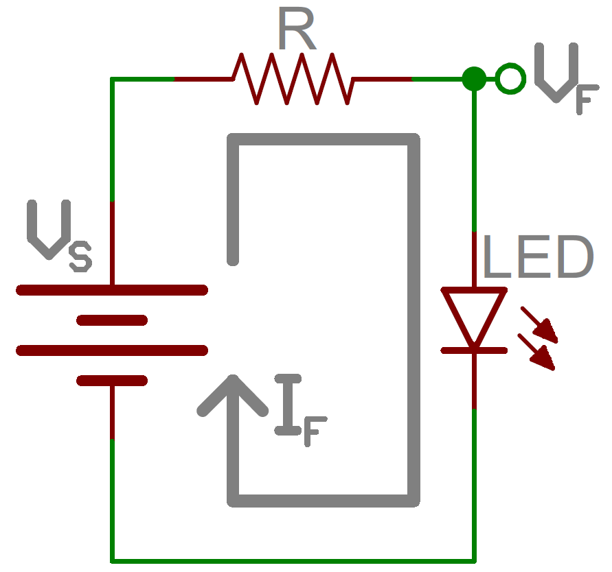
One main use of resistor as a current limiter. Resistors are key in making sure LEDs don’t blow up when power is applied. By connecting a resistor in series with an LED, current flowing through the two components can be limited to a safe value. Note the circuit given below. Resistor R is connected in series to the LED.

For calculating the value of current limiting resistor for led two important thing should be consider, the typical forward voltage (Vf), and the maximum forward current (If). The typical forward voltage is the voltage which is required to make an LED light up, and it varies (usually somewhere between 1.7V and 3.4V) depending upon the color of the LED. The maximum forward current is usually around 20mA for basic LEDs; continuous current through the LED should always be equal to or less than that current rating. Once you got the value of Vf and If the the size of the current limiting resistor can be calculated using the formula:
R = (Vs - Vf) / If
where, Vs is the supply voltage. For our case suppose we power it from 5V source and led forward voltage is 1.8 V. Then value of resistor for 10mA led current:
R = (5 - 1.8) / 10 = 320 ohm.
Voltage Dividers

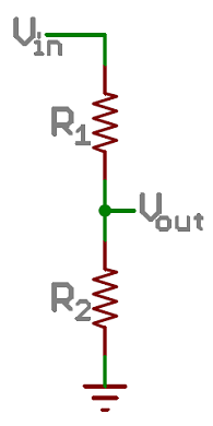
A voltage divider is a resistor circuit which turns a large voltage into a smaller one. Using just two resistors in series, an output voltage can be created that’s a fraction of the input voltage and depends on the ratio of the two resistors.
In the circuit on right side two resistors, R1 and R2, are connected in series and a voltage source (Vin) is connected across them. The voltage from Vout to GND can be calculated as:
Vout = Vin x R2 / (R1 + R2)
For example, if R1 was 1.7kΩ and R2 was 3.3kΩ, a 5V input voltage could be turned into 3.3V at the Vout terminal.
Voltage dividers are very handy for reading resistive sensors, like photocells, flex sensors, and force-sensitive resistors. One half of the voltage divider is the sensor, and the part is a static resistor. The output voltage between the two components is connected to an analog-to-digital converter on a microcontroller (MCU) to read the sensor’s value.
Pull-up Resistors
A pull-up resistor is used when you need to bias a microcontroller’s input pin to a known state. One end of the resistor is connected to the MCU’s pin, and the other end is connected to a high voltage (usually 5V or 3.3V).

Without a pull-up resistor, inputs on the MCU could be left floating. There’s no guarantee that a floating pin is either high (5V) or low (0V).
Pull-up resistors are often used when interfacing with a button or switch input. The pull-up resistor can bias the input-pin when the switch is open. And it will protect the circuit from a short when the switch is closed.
In the circuit above, when the switch is open the MCU’s input pin is connected through the resistor to 5V. When the switch closes, the input pin is connected directly to GND.
The value of a pull-up resistor doesn’t usually need to be anything specific. But it should be high enough that not too much power is lost if 5V or so is applied across it. Usually values around 10kΩ work well.
If you need resistors, you can have a look at these products:
More Electronic Component,welcome to HALJIA!

